doi: 10.56294/evk202222
ORIGINAL
Operating and maintenance manual for the implementation of the conventional drinking water treatment plant (ptap) in the urban area of the municipality of Bochalema, northern Santander
Manual de operación y funcionamiento para la implementación de la planta de tratamiento de agua potable (ptap) convencional del casco urbano del municipio de Bochalema- norte de Santander
Sara Esther Sanchez Carrillo1, Ana María Rosso Cerón1
1Universidad De Pamplona, Facultad De Ingenierías y Arquitectura, Departamento De Ingeniería Ambiental, Civil y Química. Pamplona, Colombia.
Cite as: Sanchez Carrillo SE, Rosso Cerón AM. Operating and maintenance manual for the implementation of the conventional drinking water treatment plant (ptap) in the urban area of the municipality of Bochalema, northern Santander. eVitroKhem. 2022; 1:22. https://doi.org/10.56294/evk202222
Submitted: 28-08-2021 Revised: 18-12-2021 Accepted: 02-03-2022 Published: 03-03-2022
Editor: Prof.
Dr. Javier Gonzalez-Argote ![]()
ABSTRACT
This manual describes the activities and operating and maintenance characteristics of the water supply service in the urban area of the municipality of Bochalema, Norte de Santander, which is provided by the Public Services Unit. The municipality of Bochalema has two types of water treatment plants, one conventional and one compact. The need for a manual indicating the activities and procedures for the proper operation and maintenance of the conventional plant was identified, since these activities are sometimes carried out empirically by operators, i.e., acquired through several years of experience in their positions, ignoring the importance of having a manual that supports the operational management of the plant and provides the personnel involved with adequate knowledge about the procedures that are carried out and the best way to operate the facilities, equipment, and supplies. Training both current and new managers. The specific objectives focus on: describing the parts that make up the conventional treatment plant, specifying the functioning, operation, and maintenance of the PTAP, indicating the processes and quality standards for water treatment, and preparing safety data sheets for chemical reagents. To achieve the above objectives, the training was organized into sections so that each one would allow for the development of a specific objective, based on a qualitative and quantitative analysis of the needs of the conventional treatment plant and the operators involved, in accordance with the training required for its optimal operation. Based on the above and as the main result of the project, a detailed and practical manual was produced that meets the needs, focusing on improving the quality of water supplied to the inhabitants of the urban area of the municipality of Bochalema and on good laboratory practices.
Keywords: Water Quality; Training; Pollution; Purification.
RESUMEN
El presente manual describe las actividades y características de operación y mantenimiento correspondiente al servicio de acueducto del casco urbano del municipio de Bochalema- Norte de Santander, el cual es prestado por la Unidad de Servicios Públicos. El municipio de Bochalema, cuenta con dos tipos de planta de potabilización, una de tipo convencional y otra de tipo compacta, se identificó la necesidad de un manual que indique las actividades y procedimientos para la correcta operación y mantenimiento de la planta convencional, puesto que en algunas ocasiones se realizan dichas actividades de forma empírica por parte de los operarios, es decir adquirido por varios años de experiencia en sus cargos, ignorando la importancia de contar con un manual que respalde el manejo operativo de la planta y brinde al personal que interviene, el conocimiento adecuado sobre los procedimientos que se desarrollan y sobre la mejor manera de operar las instalaciones, equipos e insumos. Capacitando a los encargados tanto los que están activos como aquellos que ingresen. Los objetivos específicos se enfocan en: describir las partes que componen la planta de tratamiento convencional, especificar el funcionamiento, operación y mantenimiento de la PTAP, indicar los procesos y estándares de calidad para el tratamiento de agua, y elaborar las fichas de seguridad de los reactivos químicos. Para lograr los objetivos anteriormente descritos, se organizaron en secciones de modo que cada una de ellas permita el desarrollo de un objetivo específico, de acuerdo con el análisis cualitativo y cuantitativo, realizado de las necesidades presentes en la planta de tratamiento convencional y de los operarios que en ella intervienen, acorde a la capacitación requerida para el óptimo funcionamiento de esta. Con base en lo mencionado anteriormente y como resultado principal del proyecto, se realizó un manual detallado y práctico que logra satisfacer las necesidades, enfocado en la mejora de la calidad del agua suministrada a los habitantes del casco urbano del municipio de Bochalema y de las buenas prácticas de laboratorio.
Palabras clave: Calidad del Agua; Capacitación; Contaminación; Potabilización.
INTRODUCTION
The technical regulation of the drinking water and basic sanitation sector (RAS) stipulates that drinking water treatment systems must have a manual that specifies and facilitates operating activities, to which plant operators responsible for the proper functioning of the system must have access. The manual must be written transparently, including direct instructions that avoid complex theoretical descriptions. It must include a detailed description of the theory of each process. In the conventional plant located in the urban area of the municipality of Bochalema, there is no manual for operators to support operational management of the plant. Therefore, the objective of this project is to create an operation and maintenance manual for implementation in the plant.
Currently, water quality is a fundamental aspect, primarily when it is intended for human consumption, there are several processes for its potabilization, however, there are shortcomings in terms of how to make water potable in infrastructure aspects and, in other cases, associated to the fact that the methodology applied does not meet the needs required by the population.(1,2,3,4,5,6,7,8,9,10,11)
Treatment systems require a chain of integral actions for their correct functioning, allowing the establishment of an operation and maintenance routine.(2,13,14,15,16,17) Consequently, the entry of new operators in treatment plants represents a problem when there are no specific documents to train them. Nowadays, training in organizations is of vital importance because it contributes to the development of collaborators both personally and professionally. Therefore, companies must develop mechanisms that equip their personnel with the knowledge, skills, and attitudes necessary to achieve optimal performance throughout the worker’s tenure within the organization.(3,18,19,20,21,22,23)
This manual corresponds to a set of instructions that are suggested for the proper management of the treatment units present in the conventional plant in the urban area of Bochalema. The contents of the manual are made up of 4 sections, in the first one there is a description of the infrastructure and the drinking water treatment stages, in the second one there is a specification of the operation and maintenance for the correct functioning of the system, in the third one the processes and quality standards for water treatment are specified, and finally the safety data sheets of the reagents were prepared and the equipment calibration process is indicated.(24,25,26,27,28,29)
How can an operation and maintenance manual be prepared to facilitate the correct operation of the conventional drinking water treatment plant in the urban area of the municipality of Bochalema, in the absence of a technical document to guide the operators?
Objective
To elaborate an operation and maintenance manual for the implementation of the conventional potable water treatment plant (PTAP) of the urban area of the municipality of Bochalema- Norte de Santander.
METHOD
The methodology used for developing the WTP operation manual is presented below. The study for the project is of an investigative and field type, involving the collection of data through the inspection of the plant and its current operation.
Stage 1: Information gathering - bibliographic review
It began with a bibliographic and theoretical review, seeking information from internal sources, that is to say, within the company, such as the verification of the archived documentation concerning the conventional water treatment system and sampling applied, as well as characteristics of the municipality, thus obtaining a starting tool for the knowledge of the processes that have been carried out, evidencing that within the company there is outdated documentation, for this reason it is necessary to make updates, since with the intervention of the optimization project many of the structures have been modified. At the same time, external sources were searched for books related to the water treatment system, operation and maintenance manuals with similar plants taking into account capacity, such as flow, population, and water treatment processes, review of articles and other normative documents in force in the national framework that allowed enriching the content of this manual.
Stage 2: Description of the infrastructure and stages of the water purification process
With the collection of information carried out in stage 1, referents of the conventional plant were identified, and data collection methods, including interviews, observation, and field measurements, were employed. Information was obtained directly from the municipality’s water company, operator, plumber, and inhabitants, as well as from other primary sources, including organizations related to the research object (service providers, the municipal mayor’s office, and the government of Norte de Santander). The data collected were both measurable and observable, as well as inferred and extracted from verbal language.
We began by making a summary table of the infrastructure of the treatment plant before the intervention in which the changes can be seen and a description was made of the improvements presented in the infrastructure, that is to say, the current panorama, It should be clarified that to date the PTAP is not in operation given that the “optimization of the municipality’s urban aqueduct system” project is 85,55 % complete.
Stage 3: Specification and verification of the functioning, operation, and maintenance of the PTAP
A description of how each of the stages of the plant works and how it is maintained was provided, taking into account the adaptations that must be carried out for the optimal operation of the plant, allowing guidance on the importance of each of them, and the optimal operation of the parts involved in the drinking water treatment process.
Stage 4: Specification and review of standards in each of the processes
A review was conducted of Decree 1575 and Resolution 2115 of 2007 to verify the water quality standards required for the plant.
To investigate the quality of the source within the company, water samples were taken, revealing that the source is deficient, indicating poor water quality.
Stage 5: Preparation of safety data sheets for chemical reagents and calibration of equipment
Safety data sheets were prepared based on literature documents on process safety so that the operator has the necessary information and is aware of the recommended safety procedures.
Stage 6: Preparation of the operating manual
In this activity, the final document was elaborated, which encompasses all previous activities, allowing the operator to refer to it for training and instruction on aspects of plant operation. This enables them to clarify any uncertainties that may arise.
RESULTS
This manual provides a guide of recommended procedures for the proper management of the treatment units, starting first with a summary of the characteristics of the plant and illustrating its distribution using a layout, in the following sections the specific objectives are worked on, The following sections describe the specific objectives, starting with a description of the infrastructure and the drinking water treatment stages, specifying the operation and maintenance for proper operation, and the physical, chemical and microbiological parameters according to current regulations.
Plant characteristics (Layout)
Figure 1 illustrates a schematic of the conventional plant infrastructure, providing an overview of its layout and the various components that comprise it. The drinking water treatment process comprises several stages, starting with the collection, adduction, pretreatment, treatment, and later distribution of drinking water.
The process begins with the catchment, where through a structure known as a dam intake catchment, which extends from side to side of the stream whose catchment area is located on the crest of the central spillway, which is provided with a grid for the passage of water, After the intake, the water is directed to the adduction, which is a component of the system for transporting raw water to the sand trap, where suspended material, especially sand, is removed. The removal of floating material and suspended material is carried out to prevent damage to subsequent structures or equipment; this process is known as pretreatment.
Then follows the process of coagulation-rapid mixing that is done by adding a chemical substance known as coagulant, whose function is the destabilization of the particles that usually surround or are present in the water, through a jar test, different water samples are taken, and by applying coagulants in different proportions will choose the one that yields better results in terms of removal. Additionally, in some coagulants, it is necessary to adjust the pH (at a low cost). In the treatment plant, it is carried out in a unit known as a rapid mixer.
Then follows flocculation, where the destabilized particles are gathered to form agglomerations of greater weight and size (floccules). To promote the growth of these floccules, the water is passed through chambers in the Alabama-type flocculator, where flocculation takes place.
Alabama type flocculator, where the orthokinetic flocculation takes place based on the collisions of the particles caused by the movement of the water.
In the process of sedimentation by the effect of gravity the particles that by their weight are directed to the bottom, the settler is laminar is provided with spillways where the top layer of water is captured, passing to the filtration zone where through the quick filter, the particles that were not sedimented are retained and obtaining filtered water in the superficial part, which is conducted to the slow filter where in this the filtration has a descending flow that is to say the filtered water is collected in the bottom by a perforated pipe.
It then undergoes the disinfection process, where a solution of granular chlorine is applied to eliminate the remaining microorganisms in the water. Finally, it is stored in a distribution tank and distributed to users.

Figure 1. Layout PTAP Topaz
Description of the infrastructure and stages of the drinking water treatment plant process
In this section it is important to highlight that the conventional plant has undergone a series of modifications as a consequence of the improvements in the infrastructure for the optimization of the plant’s processes. Table 1 shows what its structures were prior to the intervention of the 2018 water consortium.
|
Table 1. Structures of the Conventional Plant Before the Optimization Intervention |
|
|
Stage |
Illustration |
|
Catchment: The catchment is provided with a structure that goes from side to side of the creek, it has a grid of 0,70 m long, and 0,50 m wide provided with rods with a diameter of 1,59 cm separated every 5 cm built in 1960 for a flow of 35 l/s.(5) The Aduction is carried out by means of a 10-inch diameter PVC pipe a length of 76 meters from the catchment to a break chamber from which two 6-inch pipes in PVC and HF (cast iron) with a length of 36 m to the desander The pipeline was damaged in some sections, it is uncovered along its route.(4) |
|
|
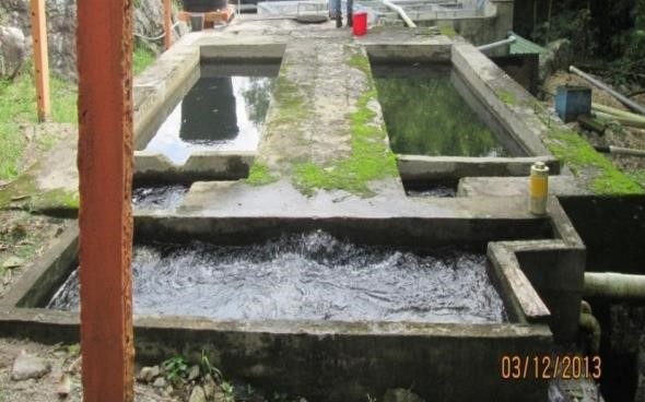
Desander: The desander is of the conventional type, the desanding area has two tanks in parallel with dimensions 4,50 m long, 1,50 m wide and variable depth of 2 m at the ends and 2,5 m in the center. on the other hand it presented internal filtrations loss of captured water.(4) It had wetlands and leaks, and was at risk of stability.(5) |
|
|
Treatment Plant: It has the processes of rapid mixing-flocculation, sedimentation, filtration and chlorination. It needs structural reinforcement and structural maintenance works.(4) |
|
|
Rapid mixing-Flocculator: Chemicals: aluminum sulfate type A is dosed by drip that is done gravity by means of a PVC dosing tank.(4) |
|
|
Alabama type flocculator: composed of 9 chambers of 1 m wide by 1 m long and 1,9 m deep, it presented internal filtrations.(4) |
|
|
Settling tank the collection of settled water is carried out in each unit by means of sawtooth gutters, presented filtration problems.(6) |
|
|
Rapid filtration There were problems with the filtering bed layers were mixed granulometries Layer of 1 m thick.(4) |
|
|
Storage tank It is of buried type Built in concrete, it has vents, inlet outlet and purge valves. The dimensions are 8,80 m long, 8,70 m wide and 3,40 m deep (260 m3). Capacity assessment (total usable storage volume of 230m3.(4) Tank 2 is located next to the compact PTAP on the property of the José Rozo Contreras school, the storage tank is a buried type in concrete that has dimensions of 12 m long, 12 m wide and 2 m deep for a capacity of 288 m3, located in the upper part of the hull. The storage tank has cracks and fissures, and there is algae inside the structure.(6) |
|
|
Sludge and drainage treatment: the Treatment Plant does not have sludge treatment, the leftover water from maintenance and cleaning is discharged directly into the Quebrada.(4) |
|


Potabilization processes are understood as the set of operations performed on raw water to modify its physical, chemical, and microbiological characteristics in order to make it suitable for human consumption.(7)
Catchment stage
The catchment works are hydraulic structures, responsible for capturing a particular flow, depending on the source of supply, a specific structure is built according to design criteria.(8) Generally, in the case of surface water, we refer to water intakes.
The water that supplies the urban area of the municipality of Bochalema is captured from a surface source (Quebrada Aguablanca), located in the village of Agua Blanca, 586 meters from the urban area. The catchment site is located at the geographic coordinates X: 1.333.130 latitude and Y: 1.156.940 longitude, at an elevation of 1146 meters above sea level. Figure 7 shows a photograph of the Quebrada catchment structure.

Figure 2. Aguablanca Creek Catchment Structure El Topacio Plant
The catchment structure is made by a concrete retaining wall, located transversely with a length of 7 meters, the catchment area is located on the crest of the central spillway, consisting of a bottom grid formed by a rectangular iron frame 0,40 m long and 0,65 m wide, with 8 iron pipes of 1 inch in diameter, which have a separation between them of 0,05 m. For better understanding, figure 8 shows the scheme with the main dimensions described here.

Figure 3. Schematic diagram of the intake-bottom intake(4)
Adduction stage
It involves the transport of water by gravity or pumping from catchment sites to treatment plants, providing a service of raw water supply along its route.(8)
The addition is carried out using a 10-inch diameter PVC pipe that operates by gravity. It has a length of 76 meters from the catchment to a break chamber, from which two 6-inch PVC pipes extend, each with a length of 40 meters, to the sand trap. The breakage chamber is located about 40 meters away from the sand trap. Its structure consists of a 20 cm thick concrete reinforcement, measuring 1,40 meters wide, 1,90 meters long, and 1,70 meters high. The importance of this structure lies in reducing the pressure with which the raw water is transported from the catchment to the desander, as it is conducted by gravity. Consequently, there is an increase in pressure upon arrival at the desander due to the height difference.(9)
Pretreatment stage
When water comes from rivers or streams, it is normal for it to carry sand or suspended matter. To eliminate it, it is necessary to build between the catchment and the distribution tank a series of infrastructures that carry out some processes that transform raw water as raw material, into drinking water as final product, among these is the desander, whose function is to retain suspended materials mainly sand, to avoid damage to the valves, additionally they facilitate that through the retention of suspended coarse solids the process of clarification of the liquid is initiated.
Desander
A desander can have different zones as shown in table 2 When entering the Topaz plant the first structure that is found is a desander consisting of the zones shown in table 2, the sludge zone, is designed under a funnel system at the bottom of the desander, This is activated by suction of the deposited precipitates, which are extracted by valves that direct the material to the stream bed. Each module of the sand trap features a weir, protected by a concrete cover; the outlet of the weirs is connected to the sludge and sediment extraction pipe.
|
Table 2. Desander Zones, Verification and Observations(8) |
||||
|
Zones |
Description |
Yes |
No |
Observations |
|
Stilling chamber |
It is the chamber where the energy of the water that arrives with some velocity from the catchment is dissipated. The passage of the water to the next zone can be done by means of a distribution channel with submerged orifices. Laterally there is an overflow spillway that carries the excess flow back to the river through a pipe that connects with the washing zone. washing |
X |
|
Velocity reduction |
|
Sand trap inlet |
It is formed between the stilling chamber and a curtain which forces the flow lines to descend rapidly, so that the initially coarser material settles out. the coarser material is initially sedimented. |
X |
It consists of 25 inlets of 2" diameter. |
|
|
Sedimentation zone |
Place where all the remaining particles settle and where the laws of sedimentation are strictly complied with. |
X |
The structure has a depth of 2,78 m, therefore it is recommended not to exceed 30 cm of sedimentation according to the RAS (total volume of sedimentation). desander total volume) |
|
|
Desander outlet |
It consists of a submerged screen, the outlet spillway and the collection channel. The bottom has longitudinal and transverse slopes transversal slopes towards the washing pipe |
X |
2 outlet weirs and collection channel. |
|
|
Sludge storage |
It comprises the volume between the useful depth in the sedimentation zone and the bottom of the tank. |
X |
Excess water from maintenance and cleaning is discharged directly into the Aguablanca stream Aguablanca Creek. |
|
Figure 4 shows the pipe coming from the breaker box, where it enters the sand trap.

Figure 4. Entrance channel to the desander
A few meters after the intake (116 m) is the sand trap (figure 5), made up of two parallel concrete modules, with two gates, two drainage valves and a direct passage (bypass). The wash water from the sand trap is evacuated through an open channel, whose receiver is the creek.

Figure 5. Sand trap structure
Treatment stage
In a drinking water treatment plant, it is essential to know the flow of water to be treated, and there are several ways of measuring this flow, one of which is by means of a hydraulic structure known as a Parshall flume. This measurement is contemplated in Colombian technical standard NTC 3933, standard method for measuring flow in open channels with Parshall flumes.
Coagulation
The objectives expected during the clarification stages are: the elimination of suspended solids, the elimination of pathogenic microorganisms and the correction of the physicochemical characteristics that make the water unfit for consumption, so that the colloids can be removed from the water, two actions must be carried out which is the destabilization of the colloids through the addition of coagulant and the aggregation of the colloids through flocculation.(11)
Parshall troughs consist of a rapid change in slope and shrinkage or constriction in the throat that produce a hydraulic upset, this upset helps turbulence to occur, which is necessary for the application of coagulants in the rapid mixing process.(12)
The Parshall flume is provided with three sections, the first is a convergent zone where the water from the desander enters through a 6-inch PVC pipe, the second consists of a gate that facilitates the mixing of aluminum sulfate as a coagulant thanks to the effect of slope change turbulence is produced and finally there is the divergent section where the velocity decrease occurs to subsequently move on to the flocculation process. Figure 11 shows the Parshall flume with two hydraulic projections, the first one of 30 cm and the next one of 50 cm.

Figure 6. Inlet pipe and Parshall flume
Flocculation
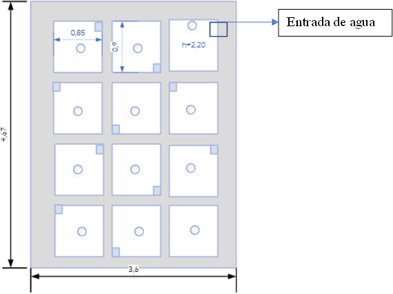
Figure 7. Alabama Type Flocculator Schematic Diagram

Figure 8. Parshall flume and Alabama type flocculator
Flocculation or slow mixing is a gentle agitation process whose main objective is to gather the coagulated particles of greater weight and size called flocs, which allows them to be removed more easily in the sedimentation process.(12)
This process is carried out by means of an Alabama type flocculator, the flocculator is built in concrete, it is a vertical flow hydraulic type, designed with twelve chambers each with its respective screen or elbow, they are located alternately, fulfilling the characteristics of an Alabama type flocculator. Each chamber has a plug that allows the extraction of sludge, a representation was made in figure 7, according to what was evidenced in the inspection of the structure.
In the Alabama flocculators, an elbow must be placed in each chamber to push the fluid upwards. The elbows should be placed alternately, in one chamber on the right and in the next chamber on the left. At the bottom of each chamber there is a drain, which is connected or linked to each chamber to allow the elimination of the sludge is removed by the operation of a valve that allows the extraction of the sediments coming from the twelve chambers of the flocculator.
Sedimentation
This consists of settling the floccules formed in the previous process and by the action of gravity they precipitate to the bottom in the form of sludge, resulting in more clarified water on the surface. The settled water can be collected by means of an overflow weir system of overflow weirs and perforated pipes that are connected.
The lamellar settler is divided into several zones or parts as shown in figure 14, a water inlet zone, a sedimentation zone consisting of plates installed with an angle of inclination of 60º but can also be values up to 45º (in the case of sedimentation of sands or heavier particles), in order to ensure a continuous and efficient removal of sludge. A sludge extraction zone and an outlet or spillway zone in which the upper water is captured from the water that contains less turbidity or is more clarified.(13)

Figure 9. Parts that make up a Laminar Settler(13)
After the flocculation process, it is taken to a lamellar settler that has two parallel sections called vessels built in concrete, which are provided with a row of modules formed by sedimentation panels installed at an angle of 45° made of polypropylene in a “parallelogram” or “beehive” shape. Each module has sludge collection hoppers at the bottom. The clarified water flow in each vessel is ascending and is transported through a system of PVC pipes with perforations in the upper part, then it is directed to a chamber, in which the four perforated pipes are pouring, see figure 10, and from there it is taken to the next stage of rapid filtration through a 6-inch PVC pipe.

Figure 10. Laminar Settler
Filtration
Filtration is one of the operations carried out in any treatment plant, consisting of retaining suspended and colloidal particles that have not sedimented by passing them through a porous medium.
The purpose of the rapid filter is to retain suspended solids through several layers of stone material of different granulometries, which decrease in the direction of flow. In this type of system, the water is forced to flow upward through the different layers of filter material (such as library books).
The water coming from the laminar sedimenter is conducted through a 6-inch pipe to a distribution box that is centered, which is directed through two sections of horizontal channels to each of the ends of this, feeding a rectangular structure that is provided at the bottom of a 6-inch pipe that leads the liquid to the bottom of the filters where the process of ascending filtration begins. At the end of the structure, there is a water outlet channel where the water from the two filtration units is collected, and an additional bypass inlet from the flocculator is activated by a valve, as shown in figures 11 and 12.
Two eight (8) inch pipes come out of the quick filter structure and are directed to the backwash structure, one pipe corresponding to the right unit and the other pipe to the left unit of the filter. In the backwash structure, there are two ball valves to control the backwash evacuation flow. There are also two orifices for draining each filtration unit. The inlet valve to the filter is closed, and by opening the ball valves, backwash is directed to the filter.

Figure 11. Upflow Fast Filter

Figure 12. Fast Filter with Dimensions
The ball valves are closed and by opening the ball valves, the backwash is performed by evacuating the filtered water film that has been deposited on the surface of the filter, in the opposite direction (downward) to its regular operation, evacuating the sediments retained by the filter bed, thus providing maintenance in the fast filtration structure.
The slow filter structure is followed by the fast filtration structure, which is comprised of 2 units with a silica sand filter bed. The slow filtration structure is larger than the previous filter and, as its name indicates, the filtration velocity is lower; figure 13 shows a general representation of the slow filter and its dimensions.

Figure 13. Slow filter structure and dimensions
Disinfection
Disinfection is carried out in a unit located after the slow filter, and is the last process of the water treatment stage, whose objective is to guarantee water quality from a microbiological point of view and ensure that it does not cause harm to the health of consumers;(14) it is one of the most important tasks in a treatment plant.
Disinfection involves the direct application of chemical substances to water or the use of a physical agent to destroy pathogenic microorganisms that can transmit diseases to the human organism. In this particular case, granular calcium hypochlorite is applied through a PVC tank, where the respective hypochlorite solution is dispensed according to the predetermined dosage for effective disinfection.

Figure 14. Disinfection Unit
Distribution Stage
The storage or distribution tank helps ensure the water supply by allowing it to be stored for use during peak demand times and seasons.
Due to the need for a good water supply in the upper parts of the urban area, two storage tanks with a capacity of 250 m3 and 100 m3 have been installed, the latter of which is currently constructed as shown in figure 15.

Figure 15. New Storage Tank
Functioning, operation, and maintenance of the drinking water treatment system.
Catchment
Operation
During the collection process, a large amount of liquid is received. The larger solids found in the water, such as leaves, branches, trunks, stones, and plastics, are retained by a screen.
They are retained thanks to a screen. In this first stage, it is of utmost importance to clean the screen, as these materials hinder the passage of water.
Operation
· Check flow variations and changes in the physicochemical properties of the water.
The review of the flow is important since for the good operation of the plant it is necessary to know the flow that will be treated, since, if the water that enters the plant exceeds its capacity, it will entail that it will not leave well treated, in addition the verification of the source is of extreme importance, since the water is a liquid whose properties change (winter and summer seasons, and that in its trajectory it can bring elements that are causing contamination).
· According to the capacity of the WTP, open or close the valve or gate to regulate the entry of water into the system.
· Verify the functioning of the valves in each operation and lubricate them periodically every three months.
· Interrupt the service when the water is very cloudy or has much mud, especially when there is heavy rainfall, as the turbidity levels are affected.
· Schedule cleaning or maintenance activities of the surroundings every three months.
Maintenance
· Clean the grates.
· Remove with a shovel the sedimented sand inside the intake.
· Recommended maintenance should not be less than one week.
Adduction
Operation
The adduction line must be examined along its entire route for leak detection and verification of its condition once a week, which is considered a preventive activity. Additionally, the soil conditions near the addition lines must be considered.
Corrective maintenance
Repair due to pipe breakage, this maintenance is eventual, since it is unknown when damage to the pipe may occur.
Desander
Operation
The water coming from the addition enters through the 6-inch PVC pipe.
· The fluid descends due to the stilling wall, and the coarser material (sand-gravel) settles.
· In the sedimentation zone, the finer particles settle until they reach the sludge zone.
· The sludge zone retains the particles that were sedimented and can be expelled by opening the valve of the washing pipe.
· The outlet zone of the sand trap consists of a weir that flows into an open channel.
The water with the least amount of coarse particles exits to the following process through a 6-inch PVC pipe.
Operation
In typical operation, the bypass and drain valves should be kept closed, and the inlet and outlet valves to the sand trap should be kept open. It is important to mention that the sand trap is located in an area where leaves are constantly entering, therefore the operator must inspect and remove those materials that are floating on the surface of the water, and it is also recommended to install a protective material (Polyshade) on the structure to mitigate the entry of objects in the process.
Inspection of the structure and its operation, the condition and operation of the structure and inlet and outlet accessories are inspected to ensure that they are not broken (signs of cracks) or show any abnormality.
Maintenance
Close approximately 90 % of the main inlet valve to the sand trap, leave a slight flow at the inlet for subsequent rinsing, and follow the scheme shown in figure 16 to perform maintenance on the sand trap.

Figure 16. Desander maintenance
Coagulation
Operation
Water from the sand trap enters through a 6-inch PVC pipe into the reception channel of the Parshall flume. The water continues its journey until it reaches the convergent zone of the Parshall flume:
· Flow measurement is performed thanks to a gate with a graduated ruler.
· The aluminum sulfate is dosed using a hose that transports the solution from a 1000-liter dosing container.
· The electric pump is activated, and its function is to supply the optimum programmed and adjusted dosage quantity according to the requirements calculated in the jar test.
· The location of the hose is verified, making sure that it is located before the shoulder to take advantage of and ensure that the mixture is homogeneous.
· Finally, it continues to the divergent zone of the trough, where it is directed to the flocculator.
Importance of pH in water
In a water supply system, the pH level at which the water enters is of utmost importance. The scale ranges from 0-14, with acidic pH, the range from (0-7), a pH of 7 is considered neutral, and the range from (7 -14) basic. The pH influences treatment such as coagulation, disinfection, and corrosion control.
In the dosing processes for pH regulation, caustic soda flakes are used. This substance is applied using a dosing pump and an injection hose. The dosing pump is electrically operated. It sucks the caustic soda solution from a 1000-liter tank and ejects it through a hose to the divergent zone of the Parshall trough. The dosage is graduated according to the result of the jar test.
Operation
· Check that there is sufficient reserve inventory in the chemical tank. This can be adjusted or estimated according to the meteorological variations presented, ensuring compliance with the quality standards required for operating in the PTAP.
· Verify the availability of treated water to form the coagulant solution, taking into account that the tank has a capacity of 1000 liters.
· Check the working condition of the dosing equipment.
· Inspect the equipment for the realization of the test of jugs, pH meter, and turbidimeter.
· Adjust the dosing unit according to the inlet flow and the dose to be applied, according to the jar test.
· Verify that the solution container is in optimal conditions (no leaks). Open the water valve until the necessary flow is supplied to the container to form the coagulant solution with the optimum dosage.
· Verify that there are no obstructions in the pipe that conducts the coagulant solution to the quick mixer.
· Verify that the optimum dosage was applied in the Parshall trough at the point of highest turbulence.
· Measurement of the flow rate in this activity, the operator in charge has already established the required flow rate point, which should be taken into account according to the period of demand during the week, since on weekends, the flow rate is not always the same as at the end of the week.
· During the week, as weekends tend to have higher commercial activity, there is a higher supply requirement.
· Preparation and application of coagulant (performing the jar test, verifying the optimum dosage to be applied according to the change in turbidity presented).
· Dosage adjustment using caustic soda and coagulant dosing pumps: the dosage rate is adjusted using the pump regulating screw, according to the jar test.
· Periodic activities: weekly cleaning of laboratory equipment.
· Occasional activities: calibrate the equipment periodically at least once a month.
Maintenance
Cleaning of the structure is carried out using metallic brushes to remove mold and other materials adhered to the walls, as well as to clean the hatch.
Pump maintenance
Maintenance of the caustic soda and aluminum sulfate Type A dosing pumps is recommended every 6 months. If any faults are detected, regardless of their severity, they should be reported to schedule preventive maintenance as soon as possible to prevent significant damage.
Flocculator
Operation
The water enters the first chamber through a connection between the Parshall trough and the flocculator through a 6-inch hole to begin the slow mixing process, see figure 17.

Figure 17. Water inlet to the first chamber of the flocculator
This process is carried out vertically, as illustrated in figure 18, which describes the operation of the Alabama type flocculator.
· The water enters the first chamber (A) and descends to enter the second chamber (B) through a screen.
· Once the water enters the elbow of the second chamber (C), it rises through the elbow and then descends through the elbow (D) and continues its path to the third chamber (E) until it completes its path through the 12 chambers. As the water follows its path, flocs are formed.

Figure 18. Water path in the first 4 chambers of the flocculator(12)
Operation
· It should be verified that the dosing and rapid mixing are operating satisfactorily.
· It is necessary to verify that the water level in the chambers does not vary more than 10 % above or below the design level (23 cm).
· It should be ensured that the contact time in the unit is sufficient to allow the flocs to reach the appropriate size and weight, which is a function of the dosage, the velocity gradient, and the time that the jar test maintains the agitation.
· The floc size should be observed at the flocculator outlet, and the residual turbidity after settling should be determined and compared with that obtained under the same parameters in the jar test.
· Maintain the design flow rate constant, in order to guarantee an adequate floc (size) in which the effect of the aluminum sulfate is as optimal as possible, allowing a better clarification process by separating the colloidal particles.
· To check the floc formation at the end of the flocculator, in which it is evidenced that the dosage applied is correct by taking a sample to compare it with the one obtained previously in the jar test.
Maintenance
Wash the unit periodically, it should be scheduled every three (3) months, because it affects the operation of the PTAP (it is required to suspend the water intake) to wash the unit, close the inlet valve, and drain the unit.
Sludge removal and disposal: Sludge is removed when the flocculator is being washed, and it is expelled by manipulating the plugs of each chamber, utilizing the water pressure through the emptying and washing pipe.
Sedimentation
Operation
It is the removal by gravitational effect of the particles in suspension in a fluid, which have a specific weight greater than that of the fluid. Sedimentation is carried out in decanters. In them, the flocculus settles, which precipitates to the bottom of the decanter, forming sludge. Typically, the water velocity retention in this zone lasts 40 minutes to one hour. The decanters or settlers in their final section have weirs, which capture the upper layer of water containing less turbidity. Through these weirs, the water passes to the filtration zone.
Operation
The floc is trapped in the modules or sedimentation hives, where it slides down the walls of the channels. This process allows the floc to be trapped at the bottom, allowing the clarified water to be driven to the surface and channeled through the perforated tubes. In contrast, the floc accumulates at the bottom and is removed later during the cleaning of the settler, which is done when it is observed to be dirty due to its operational activity.
· Adequate distribution of the total flow among the sedimentation units.
· Verify that there are no broken or displaced plates that could increase the velocity of water through the sedimentation zone (figure 10).
· A uniform collection of the settled water, both between the different collecting pipes or channels, as well as along the same pipe or channel.
Maintenance
· Washing of the units. In this activity, the retained sludge is expelled through a drain valve, and the structure is also washed using a hose that expels pressurized water. This washing process includes cleaning the inclined plates. It is recommended that this be carried out every three (3) months during the summer season and every month during the winter season.
· The washing of the sedimentation unit should be programmed in advance and preferably in the summer season. The washing is started by stopping the total operation of the PTAP, then opening the inlet valve. Subsequently, when the unit is empty, start with the sludge deposit area and check the drainage channel, starting with the washing using pressurized water. Wash the sediment water collection channels and open the valves once the washing is finished.
Filtration
Fast Filtration
Operation
Conventional rapid filters consist of a structure where a filter media, in this case gravel, is placed (with different granulometry). Generally, coarser materials are placed at greater depths, while finer materials are used at lower depths. As mentioned in the description, the water arrives through the gutters to the inlet chambers and is distributed through the perforated pipe at the bottom of the filter; from there the water rises through the layers of gravel to the surface, from where it is directed to the outlet chamber, to be conducted to the slow filter.
Slow Filtration
Operation
This process is carried out in two units, utilizing slow sand filters. Figure 19 shows the components of the filter, the water enters through a pipe to the central structure, where the liquid is distributed in each of the two filtration modules, the water enters through the surface of the sand, where a biological layer has developed (at least 2 months after the filter starts operating), Its primary function is the elimination of microorganisms and the reduction of turbidity levels, it descends through the filtering bed composed of silica sand (1,7 m thick), when it reaches the bottom it is captured by a drainage system consisting of ten (10) inch perforated pipes, where the fluid is directed to the disinfection process. Specific maintenance of the filter bed is performed by scraping every year.

Figure 19. Slow filter components
Operation
· Check all the filter operating elements.
· Carefully check valves and gates, verifying the required water inlet for the operation.
· Replenish the sand that has been lost in the washings (quick filter).
Maintenance
· Daily backwashing of the quick filter (5-10 min).
· Change the filter bed eventually, when deficiencies are observed in the process.
· Repair the infrastructure when there are cracks in the walls, apply anticorrosive paint and waterproofing material, when the operator detects these events by inspection.
Chlorination
A PVC tank is used to prepare the respective hypochlorite solution, based on the predetermined dose for effective disinfection. A pipe runs from the tank to the chlorination area, where it is mixed with the water from the slow filter.
Storage tank
Operation
The storage tank is used to compensate for variations in consumption throughout the day, maintain and balance pressures in the network, and store a certain amount of water to meet emergencies or interruptions caused by damage to the aqueduct.
Operation
· Measure the distributed flow.
· To measure the flow of water entering the tank.
· Control the quality of the stored water.
· Emptying and washing the tank when sediments are detected.
Maintenance
Washing of the tanks is performed three times a year. The Tanks are emptied to facilitate the procedure.
Description of quality standards
Table 3 presents a classification of water supply sources based on physical, chemical, and microbiological characterization parameters, as well as the recommended minimum degree of treatment.
Source water quality should be characterized as completely as possible to identify the type of treatment required and the primary parameters of interest during both dry and rainy periods. Treatability tests or also called jar tests are mandatory for any level of complexity, not only for the design process, but also daily, during the operation of the plant due to changes in its quality (Reglamento Técnico del Sector de Agua Potable y Saneamiento Básico RAS, Titulo C, Sistema de Potabilización, 2000) and are intended to simulate 3 of the processes that are central to the treatment of water for human consumption, which are coagulation, flocculation and sedimentation.
|
Table 3. Source Quality |
||||
Quality level according to the degree of contamination |
||||
|
Oxygen dissolved oxygen mg/L |
≥4 |
≥4 |
≥4 |
<4 |
|
Turbidity (UNT) |
<2 |
2-40 |
40-150 |
≥150 |
|
|
Source acceptable |
Source fair |
Deficient source |
Very poor source |
|
Parameters |
||||
|
|
||||
|
Average monthly mg/L |
≤1,5 |
1,5-2,5 |
2,5-4 |
>4 |
|
Maximum daily mg/L |
1-3 |
3-4 |
4-6 |
>6 |
|
Coliforms (NMP/100mL) |
|
|
|
|
|
Average monthly |
0-50 |
50-500 |
500-5000 |
>5000 |
|
|
|
|
|
|
|
Average PH |
6-8,5 |
5-9 |
3,8-10,5 |
|
|
|
|
|
|
|
|
Color true (UPC) |
<10 |
10-20 |
20-40 |
≥40 |
|
|
|
|
|
|
|
Chlorides (mg/L-Cl) |
<50 |
50-150 |
150-200 |
300 |
|
Fluorides (mg/L-F) |
<1,2 |
<1,2 |
<1,2 |
>1,7 |
|
Treatment processes used |
(1) =Disinfection +Stabilization |
(2) =Slow filtration or direct filtration+(1) FIME |
(3) =Pre-treatment + [coagulation + flocculation + sedimentation +fast filtration] or FIME]+(1) |
(4) = (3) +Specific treatments |
|
Note: FIME Multistage Filtration |
||||
Figure 20 shows how to obtain the optimum dose of coagulant to be applied according to the conditions under which the water enters the rapid mix.

Figure 20. Methodology for Obtaining the Optimum Coagulant Dose
Coagulants are substances that when dissolved in an aqueous medium dissociate their components from a chemical point of view in an aqueous medium and form charged ions, those of positive charge called (cations) and those of negative charge (anions), it has been found that these positively charged ions are related to a series of ions of opposite charge (anions) such as chlorides, sulfides, sulfites, nitrates and nitrates, sulfides, sulfides, sulfites, nitrates, nitrites (the particles that form the turbidity and color of natural waters, have electrical charges that are usually negative), finally by their differences in terms of charge will unite and form what is known as coagulum.
Laboratory Test
To determine the physical, chemical, and microbiological characteristics of the source water, laboratory tests are necessary. Through these tests, it is possible to evaluate the conditions of the raw water and make the necessary adjustments and procedures to provide consumers with drinking water suitable for human consumption.
A Jarras test simulates the processes of coagulation and flocculation that promote the elimination of suspended colloids and organic matter that can lead to problems of turbidity, odor and taste, which are considered as physical characteristics to be taken into account for the evaluation of water quality, Therefore, we will now go into the characteristics that must be evaluated within the current legal regulations established in resolution 2115 of June 22, 2007, which introduces the concept of the risk index of water quality for human consumption (IRCA), so it is worthwhile to provide an in-depth analysis of each of the characteristics present in the evaluation of water quality.
Chapter II of Resolution 2115 shows the physical characteristics that are taken into account for the evaluation of the IRCA for the El Toppacio WWTP, in which compliance with the established parameters is verified, as shown in table 4.
|
Table 4. Physical Characteristics of Water for Human Consumption |
||
|
Physical Characteristics |
Expressedas |
Maximum acceptable value |
|
Apparent Color |
Platinum Cobalt Units (PCU) |
15 |
|
Odor and Flavor |
Acceptable or not Acceptable |
Acceptable |
|
Turbidity |
Nephelometric Turbidity Units (NTU) |
2 |
Among the characteristics evaluated, we also find the chemical characteristics that have a recognized adverse effect on human health, which are shown in table 5, together with their maximum acceptable value.
|
Table 5. Chemical Characteristics with Recognized Adverse Effect on Human Health |
||
|
Elements, chemical compounds, and mixtures of chemical compounds other than pesticides and other substances |
Expressed as |
Maximum Acceptable Value (mg/L) |
|
Antimony |
Sb |
0,02 |
|
Arsenic |
As |
0,01 |
|
Barium |
Ba |
0,7 |
|
Cadmium |
Cd |
0,003 |
|
Free and dissociable cyanide |
CN- |
0,05 |
|
Copper |
Cu |
1 |
|
Total Chromium |
Cr |
0,05 |
|
Mercury |
Hg |
0,001 |
|
Nickel |
Ni |
0,02 |
|
Lead |
Pb |
0,01 |
|
Selenium |
Se |
0,01 |
|
Total Trihalomethanes |
THMs |
0,2 |
|
Polycyclic Aromatic Hydrocarbons (PAH) |
PAH |
0,01 |
Likewise, in the chemical characteristics there are those which, due to their effects, it is of great importance to take into account that an increase in their levels requires decision making by qualified personnel (Chemical Engineer) to find the most adequate treatment and decrease their levels.
|
Table 6. Chemical Compounds with Human Health Implications |
||
|
Elements, chemical compounds and mixtures of chemical compounds that have implications on human health. |
Expressed as |
Maximum acceptable value (mg/L) |
|
Total Organic Carbon |
TOC |
5 |
|
Nitrites |
NO2- |
0,1 |
|
Nitrates |
NO3- |
10 |
|
Fluorides |
F- |
1,0 |
|
Table 7. Chemical Characteristics that Have Major Economic and Indirect Consequences on Human Health |
||
|
Chemical elements and compounds that have economic implications |
Expressed as |
Maximum Acceptable Value (mg/L) |
|
Calcium |
Ca |
60 |
|
Total Alkalinity |
CaCO3 |
200 |
|
Chlorides |
Cl- |
250 |
|
Aluminum |
Al+3 |
0,2 |
|
Total Hardness |
CaCO3 |
300 |
|
Total Iron |
Fe |
0,3 |
|
Magnesium |
Mg |
36 |
|
Manganese |
Mn |
0,1 |
|
Molybdenum |
Mo |
0,07 |
|
Sulfates |
SO4-2 |
250 |
|
Zinc |
Zn |
3 |
|
Phosphates |
PO4-3 |
0,5 |
The microbiological characteristics to be taken into account also include those of a microbiological nature, which must be within acceptable ranges in order not to present risks to human health.
|
Table 8. Microbiological Characteristics |
||
|
Techniques Used |
Total Coliforms |
Escherichia Coli |
|
Filtration by Membrane Enzyme Substrate |
0 CFU/100 cm3 |
0 CFU/100 cm3 |
|
< 1 microorganism in 100 cm3 |
< of 1 microorganism in 100 cm3 |
|
|
Sulfate Defined |
0 microorganisms in 100 cm3 |
0 microorganisms in 100 cm3 |
|
Presence - Absence |
Absence in 100 cm3 |
Absence in 100 cm3 |
Consequently, the consideration of factors previously described in physical, chemical and microbiological characteristics can be reflected by means of the so-called Risk Index of Water Quality for Human Consumption-IRCA, present in resolution 2115 of 2007, where the classifications of some basic factors to be taken into account can be seen, and where it is evidenced according to the weighting given on a maximum total sum of 100 points, as shown in table 9.
|
Table 9. IRCA Rating |
|
|
Characteristics |
Risk score |
|
Apparent Color |
6 |
|
Turbidity |
15 |
|
pH |
1,5 |
|
Free Residual Chlorine |
15 |
|
Total Alkalinity |
1 |
|
Calcium |
1 |
|
Phosphates |
1 |
|
Manganese |
1 |
|
Molybdenum |
1 |
|
Magnesium |
1 |
|
Zinc |
1 |
|
Total Hardness |
1 |
|
Sulfates |
1 |
|
Total Iron |
1,5 |
|
Chlorides |
1 |
|
Nitrates |
1 |
|
Nitrites |
3 |
|
Aluminum (Al+3) |
3 |
|
Fluorides |
1 |
|
TOC |
3 |
|
Total Coliforms |
15 |
|
Escherichia coli |
25 |
|
Sum of Assigned Scores |
100 |
The sum of the IRCA represents the viability of water consumption in terms of quality, and in itself, takes into account physical, chemical and microbiological characteristics set forth in Resolution 2115 of 2007, which can be detailed in table 10, where the weighting (0) corresponds to the level at which all the evaluated characteristics are met, table 11 shows the five ranges in which the risk level is divided and classified, specifying the entities involved and the consequences or measures to be implemented in the corresponding case.
|
Table 10. IRCA Classification According to Risk Level |
|||
|
IRCA Classification (%) |
Risk Level |
IRCA by sample (Notifications to be made by the health authority immediately) |
Monthly IRCA (Actions) |
|
80,1-100 |
Sanitary Inviable |
Inform the provider, COVE, Mayor, Governor, SSPD, MPS, INS, MAVDT, Comptroller General's Office and Attorney General's Office. |
Water unfit for human consumption, direct management according to its according to the competence of the provider, mayors, governors mayors, governors and national entities national order. |
|
35,1-80 |
High |
Inform the provider, COVE, mayor, governor and the SSPD. |
Water unfit for human consumption, direct management according to its according to the competence of the provider and the mayors and and the respective mayors and governors. respective governors. |
|
14,1-35 |
Environment |
Inform the supplier, COVE, mayor and governor. |
Water unfit for human consumption, direct management of the provider. direct management of the service provider. |
|
5,1-14 |
Low |
Inform the supplier and COVE. |
Water unfit for human consumption, subject to improvement. |
|
0-5 |
No Risk |
Continue control and surveillance. |
Water fit for human consumption. Continue surveillance. |
Within the operation of a drinking water treatment plant, the importance of the IRCA lies in the fact that we can appreciate the variation in each of the characteristics evaluated during a period of time, and therefore from this we can make the corresponding adjustments in the stage of the process or incident stages, it is there where the degree of risk arises and through its correct interpretation we can obtain the corresponding adjustments for the application of measures, both for failures in the infrastructure, deficiencies in the process, lack of maintenance, human factor, therefore, it is necessary that both the operators and the whole work team involved in the water purification process identify the functioning, maintenance and operation of each of the structures previously presented, in order not to affect the quality of the water, recognizing the quality standards required by the national regulations in force and complying with the most significant possible responsibility towards the consumers due to the high impact on the quality of life of the inhabitants of the urban area of the municipality of Bochalema.
Therefore, according to the guidelines provided in Resolution 2115 of 2007, which specify the frequency and number of samples required for accurate monitoring of characteristics and, consequently, the maintenance and improvement of water quality as needed.
The population in the urban area of the municipality of Bochalema is at a medium level of complexity, as stipulated in the technical regulations of the drinking water and basic sanitation sector, in the following table.
|
Table 11. Frequency of Water Quality Monitoring Sampling |
|||
|
Population served by service provider per municipality (inhabitants) |
Characteristics |
Minimum frequency |
Minimum number of samples to be analyzed for each frequency |
|
2501 a 10 000 |
Turbidity, apparent color, pH, free residual chlorine or disinfectant residual chlorine used |
Monthly |
1 |
|
TOC, Fluorides and residual of coagulant used. |
Annual |
1 |
|
|
Those physical and chemical characteristics of public health interest required by the risk map. |
According to the requirements of the risk map. |
According to the requirements of the risk map. |
|
Safety and Equipment Calibration Cards
Considering that any process involving chemical substances requires the necessary knowledge for handling and storage, it is of utmost importance to have this knowledge, as a lack of information can lead to accidents or damage to the physical integrity of the operator.
Therefore, it should be taken into account that these substances should be stored in a reagent room, independent from the other activities of the laboratory, under optimal conditions for the inputs used, therefore, it is recommended to place them on shelves and/or pallets separately and classifying them according to their characteristics as shown in the safety data sheets below. Therefore, it is recommended to organize the chemical elements according to the following indications, extracted from the guidelines for preparing the safety standards manual in chemistry and physics laboratories of the establishments.
· Oxidizing substances should be stored separately from flammable and/or combustible materials and mineral acids.
· Corrosive substances must be separated from flammable substances.
· Keep up-to-date records of stored products. The date of receipt or preparation should be indicated.
· Do not carry out transfers of flammable liquids inside the storage rooms, but in the area prepared and marked for this type of transfer in the laboratory.
· Containers of larger capacity or weight and those containing more aggressive substances (e.g., concentrated acids) should be closer to the floor.
· Large containers should be at the back and small containers at the front.
· Do not store chemicals, reagents, or solutions directly on the floor.
· Reagents and waste should be stored in a container of appropriate material -glass, plastic, metal-, compatible with the substance to be stored.
· Make an inventory of the chemical products to control the stock of reagents and their aging.
· Periodically check that the containers do not show signs of deterioration and that the label is in good condition. Do not store any reagent that lacks a safety label.
· Order and cleanliness should be maintained inside the reagent room.
Aluminum Sulfate Type A
The use of aluminum sulfate type A is employed in the coagulation process, where the particles suspended in the water are destabilized. Subsequently, due to its effect, a few seconds after entering into contact, flocculation occurs, where there is the application is performed using a solution previously prepared according to the analysis of the optimum dosage in the periodic jar test, adjusting the amount of reagent applied in the Parshall trough.
Aluminum Sulfate Safety Data Sheets
|
Table 12. Material Safety Data Sheet aluminum sulfate type a solid |
|||
|
Pictogram
|
NFPA identification
Health: blue 1 Flammability: red 0 Reactivity:yellow 0 Special hazards: white |
||
|
1. Product and company identification |
|||
|
Product |
: |
ALUMINUM SULFATE TYPE A SOLID |
|
|
Manufacturer/distributor |
: |
Productos Quimicos Panamericanos S.A plants: |
|
|
Address |
: |
Barranquilla carrera 67 (carretera a Eternit) Nº Vía 40-437 zona industrial la loma No.3 Cali (Jamundí), Km 28 via cali Popayán |
|
|
Country : |
: |
Colombia |
|
|
Phone number |
: |
(57+5)3859717 |
|
|
|
: |
(57+2)69545-71 |
|
|
2. Composition/information on components |
|||
|
The product is an inorganic salt, composed of a mixture of aluminum and ferric sulfates in the presence of different inert and insoluble minerals in water. Aluminum content 17 % Iron content : 0,75 % Basicity of Al2O3 Insoluble in water maximum : 0,5 |
|||
|
3. Hazards identification |
|||
|
Causes eye irritation. On the skin causes slight irritation. Fine material may be inhaled and cause irritation to mucous membranes. It is not a combustible product, but emits vapors when incinerated. Risk to the environment: may be harmful to aquatic life. |
|||
|
4. First Aid |
|||
|
General instructions Always provide the physician with the safety data sheet. In case of inhalation Remove to fresh air. If you feel any discomfort, seek medical advice. In case of skin contact Wash affected area immediately with soap and water. If symptoms of irritation persist, seek medical advice. In case of contact with eyes Wash affected eyes immediately with plenty of water for 15 minutes. Medical treatment necessary. In case of ingestion Do not induce vomiting. If the person is conscious and alert drink plenty of water (2-4 glasses of water) Call for medical help immediately. |
|||
|
5. Fire-fighting measures |
|||
|
The product does not burn by itself. Fire debris and contaminated extinguishing water should be disposed of according to local regulations. Avoid inhaling released vapours. |
|||
|
6. Accidental release measures |
|||
|
The material in solid form is harmless. Lime should be sprayed on the residues remaining after collecting the spilled material to avoid acidification of the soil when water currents are present. |
|||
|
7. Handling and storage |
|||
|
Store on pallets, in a place protected from moisture, heat and direct sunlight, away from strong oxidizing and reducing substances, strong acids and bases, flammable and combustible substances and organic solvents. The storage area should be fully ventilated, away from sources of heat, flame or spark and with easy access to emergency showers and eyewash. Safe storage conditions: ventilated, cool and dry places. Avoid spillage into watercourses. |
|||
|
8. Exposure control and personal protective measures |
|||
|
Use protective goggles and face masks to avoid inhalation of fine material. |
|||
|
9. Physical and chemical properties |
|||
|
Chemical formula : Al2(SO4)3 14 H2O Appearance: Granular or Powder Color: White or slightly yellow Odor: Odorless Taste: Astringent and slightly sweet Solubility in water: water soluble: 70 g in 100g of water at 20º Molecular Weight: 342,15 g/mol Melting point: ND Ignition temperature: ND Material is non-corrosive when dry; moderately corrosive when dissolved in water. |
|||
|
10. Stability and reactivity |
|||
|
The product is stable under normal storage conditions. Reacts with chelating agents. Releases toxic gases in case of fire. |
|||
|
11. Toxicological information |
|||
|
The product is orally toxic in amounts above 9000 mg/kg (LD50, rat) The product may be irritating to mucous membranes, but not lethal. |
|||
|
12. Ecological information |
|||
|
The product contributes aluminum to the soil, which is a drawback in agricultural soils. It is toxic to fish at a concentration above 6,5 g/m3. It does not contribute to COD in watercourses. It does not remain in the food chain. |
|||
|
13. Waste disposal |
|||
|
The product is not a hazardous waste. Its disposal in a sanitary landfill is not hazardous. |
|||
|
14. Transport information |
|||
|
The material is not hazardous in case of an accident. As long as it is transported in original packaging, the product does not release fine material into the environment. |
|||
|
15. Regulatory Information |
|||
|
The use of this product is not subject to specific controls. |
|||
|
16. Additional Information |
|||
|
The product has been classified as low reactivity, non-flammable and harmless to health. There are no special handling conditions, dilution in water is not dangerous. The product dissolved in water may oxidize metallic iron. |
|||
|
Responsibility It is difficult to anticipate the use of this product and therefore the information contained herein should be taken as a guideline and applied in the appropriate context. Main uses: drinking water treatment, wastewater treatment, swimming pool treatment, among others. Aluminum sulfate is one of the most widely used products in water treatment. Being a metallic salt, it reacts by forming aluminum hydroxide flocs on contact with the alkalinity of the water to be treated. |
|||


Sodium Hydroxide or Caustic Soda
It is applied in the divergent part of the Parshall gutter by means of a dosing pump and its application occurs when changes in pH outside the established standards are evidenced, mainly when there is rainfall and in the summer season.
Sodium Hydroxide Material Safety Data Sheet
|
Table 13. Material Safety Data Sheet Sodium hydroxide |
|||
|
Pictogram
|
NFPA identification
Health: Blue 3 Flammability: Red 0 Reactivity:Yellow 1 Special Hazard: White |
||
|
1. Product and company identification |
|||
|
Product |
: |
Caustic soda flakes 99 % crystal sodium hydroxide, sodium hydrate, lye. |
|
|
Manufacturer/distributor |
: |
MultiQuimicos S.A.S |
|
|
Address |
: |
Street 45 No. 25-30 Bucaramanga |
|
|
Country : |
: |
Colombia |
|
|
Telephone number |
: |
6321673 |
|
|
|
: |
3166922233 |
|
|
2. Composition/information on components |
|||
|
Specification: results NaOH: 99 % MIN Na2CO3, ppm: 0,2 % MAX Fe2O3: 9 % MAX MOL WEIGHT: 40 g/mol |
|||
|
3. Hazards Identification |
|||
|
Severe inhalant: Inhalation effects of dust or mist range from moderate irritation to serious upper respiratory tract damage depending on severity of exposure, severe pneumonitis and pulmonary edema. Ingestion: severe abdominal pain. Causes gastrointestinal irritation or ulceration and severe burns of the mouth, lips, tongue and throat which may result in vomiting with large amounts of mucous and blood. |
|||
|
amounts of mucous and blood. Skin: causes severe skin burns. Eye: severity of damage depends on exposure time. May cause severe irritation with corneal injury or disintegration of the conjunctiva and result in blindness. Chronic effects: dermatitis and continuous contact with skin may cause burns or deep ulceration. Repeated or prolonged eye contact with small concentrations causes conjunctivitis. |
|||
|
4. First aid measures |
|||
|
General instructions Always provide the physician with the safety data sheet. In case of inhalation Remove to fresh air, give oxygen and keep victim warm and at rest If you feel any discomfort, seek medical advice. In case of skin contact Remove contaminated clothing and footwear, wash affected area with plenty of soap and water for at least 15 minutes. If irritation persists, repeat washing and seek medical attention. In case of contact with eyes Immediately flush affected eyes with plenty of water for 15 minutes. Lift and separate eyelids to ensure removal of the chemical. If irritation persists seek medical attention In case of ingestion If conscious give plenty of water, do not induce vomiting, if vomiting occurs tilt victim forward. seek medical attention immediately. |
|||
|
5. Fire Fighting Measures |
|||
|
Fire/explosion hazard: non-combustible, however, in water it heats up and reacts with organic products, in contact with metals it releases hydrogen which mixed with air can cause fire or explosion. Combustion product: by decomposition it produces hydrogen. Precautions to avoid fire: containers may explode when heated. Avoid contact with incompatible materials and moisture. Fire extinguishing agents: dry chemical powder, foam or carbon dioxide. Do not use Halon or water jet. |
|||
|
6. Accidental release measures |
|||
|
Evacuate or isolate the hazardous area. Restrict access to unnecessary and unprotected persons. Use personal protective equipment, ventilate the area. Eliminate all ignition sources. |
|||
|
7. Handling and storage |
|||
|
Storage: ventilated, cool and dry places. Away from heat and ignition sources. Separate from incompatible materials. Label containers appropriately and keep tightly closed. Type of container: always use personal protection for handling, even if the exposure or activity with the product is short. Maintain strict hygiene standards, do not smoke or eat in the workplace. Know where the emergency response equipment is located. Read label instructions before using the product. Label containers appropriately. |
|||
|
8. Exposure control and personal protective measures |
|||
|
Normal use: safety glasses with side shield, face shield, helmet with visor, rubber gloves and boots, coveralls and respirator with dust filter. Emergency control: Self-contained breathing apparatus (SCBA) and full protective clothing. |
|||
|
9. Physical and chemical properties |
|||
|
Chemical formula: NaOH Appearance: White lumps, flakes or flakes, odorless. Absorbs water and carbon dioxide from the air. Color: White Odor: Odorless Taste: Astringent and slightly sweet Solubility: solubility in water, alcohol and glycerol. Molecular weight: 40 g/mol Boiling point: 1390 ºC Melting point: 318 ºC Ignition temperature: ND pH: 12-14 |
|||
|
10. Stability and reactivity |
|||
|
Stability: Unstable under normal conditions. Incompatibilities or materials to avoid. Water: yes; air: no; others: acids, flammable liquids, halogenated hydrocarbons, metals (aluminum, tin, zinc), nitrocompounds and methanol. |
|||
|
11. Toxicological information |
|||
|
Severe irritant may cause pulmonary edema and symptoms may become apparent within a few hours of exposure. hours of exposure. LDLO(oral, rabbit)=500mg/kg LD50(intraperitoneal, mouse)=40 mg/kg. Not listed as carcinogenic. |
|||
|
12. Ecological information |
|||
|
Not biodegradable. Does not cause oxygen deficiency, possible death of fish. |
|||
|
13. Disposal of residues |
|||
|
Eliminate residues with plenty of water, then neutralize remaining traces of caustic with acid (acetic). |
|||
|
14. Transport information |
|||
|
Transport information: White corrosive label with the number 8. Do not transport with substances of the following classes: explosives, solids which in contact with water release poisonous or flammable gases, oxidizing substances, organic peroxides, reactive materials, or with foodstuffs. Suspension of driving license Transport information Hazard class: white-black label for corrosive substances. Do not transport with explosive substances, substances which in contact with water can release flammable gases, oxidizing substances, organic peroxides, radioactive materials, organic peroxides, radioactive materials, incompatible substances and foodstuffs. |
|||
|
15. Regulatory Information |
|||
|
National Land Traffic Code. Decree 1344/7, modified by Law 33/86. Article 48: transporting cargo without protection, hygiene and safety measures. Article 49: transporting flammable, explosive or toxic materials at the same time as passengers or food. |
|||
|
16. Additional Information |
|||
|
The information related to this product may not be valid if it is used in combination with other materials or in other processes. It is the responsibility of the user to interpret and apply this information for his particular use. |
|||
|
It is difficult to anticipate the use of this product and therefore the information contained herein should be taken as guidance and applied in the appropriate context. MAIN USES: acid neutralization, petroleum refining, paper manufacturing, cellulose, textiles, plastics, explosives, paint and paint remover. |
|||


70 % Calcium Hypochlorite
Calcium hypochlorite 70 % is applied in the disinfection stage, in which it oxidizes the organic agents which are responsible for diseases caused by pathogens that are still in the water purification process. It is applied in the disinfection booth by means of a dosing pump.
Calcium Hypochlorite Safety Data Sheet
|
Table 14. Material Safety Data Sheet calcium hypochlorite 70 % |
||||||
|
Pictogram
|
Identification
Health: Blue 1 Flammability: Red 0 Reactivity: Yellow Special 0 Hazard: White |
|||||
|
1. Product and company identification |
||||||
|
Product |
: |
CALCIUM HYPOCHLORITE 70 % (granulated chlorine) |
||||
|
Manufacturer/distributor |
: |
CFC INOVEL Sciences Company |
A |
Camlin |
Fine |
|
|
Address |
: |
Transversal 93 No 53-32 bodega 40 parque empresarial el Dorado-Bogotá |
||||
|
Country: |
: |
Colombia |
|
|||
|
Telephone number |
: |
2239944 |
|
|||
|
|
: |
|||||
|
2. Composition/information on components |
||||||
|
Material: composition Calcium hypochlorite: 70 % Humidity: 5-10 Physical aspect: Granular powder Odor: Typical of chlorine or hypochlorite Granulometry (14-50 mesh): 90 % |
||||||
|
3. Hazard identification |
||||||
|
Danger! Highly oxidizing agent. Mix only with water. Contamination of product may cause fire or explosion. Do not add this product to any serving utensils containing residues of other products. Caution! May cause injury or death if swallowed; do not get in eyes, on skin, or on clothing. May cause burns. Avoid breathing dust. It is a nose and throat irritant. Wash hands after handling product. Keep out of reach of children. |
||||||
|
4. First aid measures |
||||||
|
General instructions Always provide the physician with the safety data sheet. In case of inhalation Remove the person who has inhaled the product to fresh air, if breathing is difficult give oxygen. Seek medical attention. In case of skin contact Wash affected area immediately with soap and water for 15 minutes while (remove clothing and shoes if contaminated). In case of contact with eyes Seek immediate medical attention Ingestion If swallowed give 3-4 glasses of water or milk. Only if the person is conscious and alert. Do not induce vomiting. |
||||||
|
5. Fire Fighting Measures |
||||||
|
Extinguishing media: water only. Special fire fighting procedures: product decomposes at 180°C releasing oxygen gas. Firefighters should wear NIOSH approved pressurized self-contained breathing apparatus. This apparatus should have a full face mask to prevent possible exposure to noxious gases. |
||||||
|
6. Accidental release measures |
||||||
|
Eliminate all ignition sources. Keep water away from spilled material. Ventilate area of leak or spill. Use appropriate personal protective equipment (section 8). Spills: Clean up spills in a manner that will not spread dust into the air. Use non-sparking tools and equipment. Collect spill for recovery or disposal and place in a closed container. Do not seal tightly. |
||||||
|
7. Handling and storage |
||||||
|
Keep in a tightly closed container, store in a cool, dry and ventilated area. Protect from physical damage and moisture. Isolate from all sources of heat or ignition. Avoid storage in wood. Separate from incompatible, combustible, organic or other easily oxidized materials. Observe all warnings and precautions listed for the product. Containers of this material may be hazardous when emptied as they retain product residues. |
||||||
|
8. Exposure control and personal protective measures |
||||||
|
Personal Respirators: (NIOSH approved) In use conditions where exposure to dusts or mists is apparent, a dust/mist respirator covering the face should be worn. In emergency or in situations where exposure levels are not known, wear a full-face respirator. Skin protection: Wear impervious protective clothing, including boots, gloves, laboratory clothing, apron or coveralls to prevent skin contact. Eye protection: wear chemical goggles and/or a full face shield where contact is possible. face shield where contact is possible. Maintain a facility in the work area for rapid washing, soaking and rinsing of the eyes. |
||||||
|
9. Physical and chemical properties |
||||||
|
Chemical formula : CaCl2O2 Appearance: Granular powder Color: White or grayish white Odor: Chlorine or sodium hypochlorite odor Solubility: Soluble in water; reacts, releasing chlorine gas. Specific gravity: 2,35 at 20°C Boiling point: No information found Melting point: Decomposes above 177ºC (350ºF) Physical state.: Granular powder |
||||||
|
10. Stability and reactivity |
||||||
|
Stability : Decomposes rapidly on exposure to air. May decompose violently if exposed to heat and direct sunlight. Thermally unstable, decomposes at 177 ºC. Incompatibilities: Calcium hypochlorite is a strong oxidizer. Reacts with water and acids releasing chlorine gas. Forms explosive compounds with ammonia and amines. Incompatible with organic materials, nitrogen compounds and combustible materials. Conditions to avoid: heat, flames, humidity, dust, sources of ignition and shock and incompatibles. |
||||||
|
11. Toxicological information |
||||||
|
Calcium hypochlorite: Oral LD50 in rats: 850 mg/kg. Has been investigated as tumorigenic and mutagenic. International Agency for Research on Cancer (IARC): category 3. |
||||||
|
12. Ecological information |
||||||
|
No information found |
||||||
|
13. Waste disposal |
||||||
|
What cannot be retained for recovery or recycling should be handled as hazardous waste and sent to a RCRA approved waste facility. Processing, use or contamination of this product may change the waste management options. Dispose of container and unUSED contents in accordance with federal, state and local requirements. |
||||||
|
14. Transportation Information |
||||||
|
Road (Ground, D.O.T). Legal Shipping Name: Calcium Hypochlorite Mixture, Dry Hazard Class: 5,1 UN/NA: UN1748 Packing group: II |
||||||
|
15. Regulatory Information |
||||||
|
Not found |
||||||
|
16. Additional Information |
||||||
|
NFPA Classifications: Health:3 flammability:0 Reactivity:1 other: OXIDIZER Hazard warning label: DANGER! Strong oxidizer, in contact with other material may cause fire. Corrosive. Causes burns to any area of contact. Harm if reactive water is swallowed or inhaled. Precautionary label: do not allow contact with clothing and other combustible materials. Store in a container making sure it is closed. Remove and wash contaminated clothing promptly. Do not store near combustible materials. Do not breathe dust or vapor. Keep container closed. Use only with adequate ventilation |
||||||
|
Responsibility It is difficult to anticipate the use of this product and therefore the information contained herein should be taken as guidance and applied in the appropriate context. |
||||||

91 % Chlorine
It is used for the elimination of algae that form in the plant infrastructure and that may clog the distribution pipes or the existing connections between the process stages, this is applied manually in the modules, it is taken into account that this is more stabilized than chlorine at 70 %.
Chlorine Safety Data Sheet
|
Table 15. Chlorine Safety Data Sheet 91 % chlorine |
|||
|
Pictogram
|
NFPA identification
Flammability: Red 0Reactivity: Yellow 2Special Hazards: White |
||
|
1. Product and company identification |
|||
|
Product |
: |
91 % Chlorine |
|
|
Manufacturer/distributor |
: |
PANAMERICAN CHEMICALS E- U P.Q.P |
|
|
Address |
: |
Cra 25 No41-25 of.103 Bucaramanga |
|
|
Country : |
: |
Colombia |
|
|
Phone number Email |
: |
(7)6327596 químicospanamericanospqp@gmail.c om |
|
|
2. Composition/information on components |
|||
|
Available chlorine: 91 %. |
|||
|
3. Hazards identification |
|||
|
Inhalation: Effects by inhalation of dust or mist range from moderate irritation to serious upper respiratory tract damage depending on severity of exposure, severe pneumonitis and pulmonary edema. Ingestion: severe abdominal pain. Causes gastrointestinal irritation or ulceration and severe burns of the mouth, lips, tongue and throat which may result in vomiting with large amounts of mucous and blood. Skin: causes severe skin burns. Eye: severity of damage depends on exposure time. May cause severe irritation with |
|||
|
corneal lesions or disintegration of the conjunctiva and result in blindness. Chronic effects: dermatitis and continuous contact with skin may cause burns or deep ulceration. Repeated or prolonged eye contact with small concentrations causes conjunctivitis. |
|||
|
4. First aid measures |
|||
|
General instructions Always provide the physician with the safety data sheet. In case of inhalation Remove victim to fresh air. Assist breathing if necessary. Seek medical advice. In case of skin contact Wash skin with plenty of water for at least 15 minutes, in case the product is wet. Seek medical advice. In case of contact with eyes Wash eyes with plenty of water for 15 minutes. Lift and separate the eyelids to ensure removal of the chemical. If irritation persists seek medical attention. In case of ingestion Do not administer any substance if the person is unconscious. Ingest large quantities of water, milk and/or egg white. Do not induce vomiting. Seek medical attention immediately. Clinical information Avoid gastric lavage and emetics Give alkaline substances (magnesium hydroxide gel, magnesium hydroxide milk). Do not give carbonates or bicarbonates. |
|||
|
5. Fire-fighting measures |
|||
|
Extinguishing media to use: use plenty of water. do not attempt to extinguish fire without special breathing apparatus (section 7). Do not use ABC or similar dry chemical extinguishers. Do not use nitrogen-containing extinguishers. Risk of violent chemical reaction. Clean equipment immediately after use. Combustion hazards: not flammable, but when heated above 230ºC it gives off toxic and corrosive gas: chlorine, chlorine, chlorine, chlorine, chlorine, chlorine, chlorine, chlorine, chlorine. toxic and corrosive gas: chlorine gas Cl2 increases the ignition of combustible materials. |
|||
|
6. Measures to be taken in case of accidental spillage |
|||
|
Individual precautions: it is necessary to use special respiratory equipment (section 8) even with small quantities spilled. Avoid contact with eyes and skin. Precautions for environmental protection: extremely toxic to aquatic fauna and flora. Methods for cleaning up: clean up with dry materials exclusively for this purpose. Place the product in its own place. |
|||
|
7. Handling and storage |
|||
|
Handling: wear rubber gloves and mask or goggles. After handling, wash thoroughly the material and clothing used in handling. Storage: do not use metal or wooden containers. Store in a dry place, whose temperature does not exceed 52ºC. Keep the container closed. If it is going to be stored with other products, take the precaution of compartmentalizing. This product should be left near the exit door and without impediments that obstruct them in case of having to take them outside quickly. |
|||
|
8. Exposure control and personal protective measures |
|||
|
Respiratory protection: use approved respiratory equipment when the risk of exposure is exceeded. It is recommended to use a full face shield. Hand protection: wear gloves. It is advisable to have a space nearby where the skin can be washed in case of contact. Eye protection: wear safety glasses. |
|||
|
9. Physical and chemical properties |
|||
|
Chemical formula: C3N3O3Cl3 Appearance: Solid (granular and pellets) Color: White Smell: Chlorine, similar to bleach Taste: Astringent and slightly sweet Solubility in water.: water solubility : 1,2 g/cm3 Molecular weight: 232,5 g/mol Boiling point/range.: not applicable Melting point/melting range: 230 ºC with decomposition Ignition temp: ND pH: 3 at 25ºC bulk density: 1,6 g/cm3 flammability: >250ºC |
|||
|
10. Stability and reactivity |
|||
|
Stability: stable under normal storage conditions, although the loss of active chlorine may be 0,1 % per year at ambient chlorine temperature. There is no risk of polymerization. Conditions to avoid: humidity and high temperatures (do not expose to more than 50ºC). Materials to avoid: Chlorinated s-triazinatriones are highly oxidizing and chlorinating agents. Therefore, incompatibility with: metals, acetic acid and acetic anhydrous, alcohols: methyl, ethyl, isopropyl, unsaturated aliphatic and aromatic compounds, amines, amides, ammonia and ammonium salts, calcium hypochlorite, dimethylhydrazine, fungicidal esters, glycerin, oils and grease, paint peroxides (hydrogen, sodium, calcium, magnesium, phenols, solvents: toluene, xylenes, etc.). Hazardous decomposition products: -Wet releases Cl2 (chlorine gas) and NCl3(nitrogen trichloride). -In the presence of ammonia gas or ammonia solutions, dangerous quantities of NCl3, a highly explosive gas, are generated. -Hydrogen peroxide reacts violently -The addition of oils and fats decomposes the product formed Cl2 and CO2. |
|||
|
11. Toxicological information |
|||
|
Irritation of eyes and nose, respiratory distress and increased adrenaline in rats. Changes in blood chemistry parameters occur upon repeated inhalation for 4 weeks. Acute oral toxicity: LD50=600mg/kg slightly toxic. Species: rat Water dermal toxicity: LD50=7600 mg/Kg practically not toxic. Species: rabbit Oral toxicity human LDL0:3570 mg/Kg Skin and eye irritation: corrosive. |
|||
|
12. Ecological information |
|||
|
General information on the behaviour of the substance in the environment: Very toxic to fish and algae. Do not discharge directly into rivers and lakes. Hydrolyzes in dilute aqueous solution, giving hypochlorous acid and cyanuric acid. |
|||
|
13. Waste disposal |
|||
|
Eliminate residues with plenty of water, then neutralize with acid (acetic acid) the remaining traces of caustic. |
|||
|
14. Transport information |
|||
|
Transport label: vehicle: label ‘’oxidizing agent’’ 5.1 Hazard classification: (ADR) vehicle: orange panel top no. 50 lower no.: 2468 class UN:5.1 no. 2468. Packing group II |
|||
|
15. Regulatory Information |
|||
|
Law 769/2002. National Land Transit Code. The cargo of a vehicle must be properly packed, labeled and packed and covered according to the regulations. Decree 1609 of July 31, 2002, which regulates the transport and handling of hazardous materials by road. |
|||
|
16. Additional Information |
|||
|
This MSDS has been prepared in accordance with the hazard characteristics reported by the manufacturer. The data contained in this MSDS are based on our best judgment regarding the proper use and handling of the product under normal conditions. The opinions expressed in this form are those of trained professionals. Any use of the product not in accordance with the information contained on the label or in combination with any other product or process is the responsibility of the user. |
|||
|
Responsibility It is difficult to anticipate the use of this product and therefore the information contained herein should be taken as guidance and applied in the appropriate context. |
|||

Equipment Calibration
pH meter
It will be carried out in its usual place of work and within the appropriate temperature margins.
First, it should be set up on a regular or daily basis using the buffer solutions available to the user. The following procedure should be followed:
The pH measuring system must be running for at least 30 minutes before starting the calibration process.
Set the manual temperature compensation to the value at which the buffer solutions are to be adjusted. This value is determined by measuring the temperature of the buffer solutions with a thermometer.
Examine the electrode to check that there are no defects or air bubbles present inside. If any are found, similarly, shake the electrode to match the temperature of clinical thermometers.
Clean the electrode externally with abundant distilled water.
Immerse the electrode (or electrodes if they are not combined) in the buffer solution at a controlled temperature. The solution used should be the pH solution closest to the internal pH of the glass electrode, which is usually pH 7.
Wait for thermal equilibrium for about 1 minute. Once the reading has stabilized, operate the calibration-standardization-asymmetry neutral point knob until the pH of the buffer solution is displayed.
Remove the electrode(s) from the solution and wash/them thoroughly with distilled water or the buffer solution that will be used next. The electrodes can be dried without rubbing.
Immerse the electrode in another beaker containing a different pH buffer solution than the previous one (pH four is usually used).
Wait for thermal equilibrium for about 1 minute. Once the reading has stabilized, adjust the slope-scale knob to align the display with the pH value of the buffer solution used.
The instrument is now set to full scale and ready to take pH measurements on substances of unknown pH. The scale has been adjusted at two points on the line that relates the potentials (mV) generated by the electrode as a function of the pH of the solutions in which it is immersed.
If the adjustment is required using another calibration point (e.g., pH 9), the points from 7 to 9 must be repeated.(23)
Turbidimeter
Insert the 0.1 NTU standard solution into the compartment of the HACH Turbidimeter, aligning the orientation mark. Close the lid and switch on the instrument.
Then, press the “CAL” button and wait for the 60-second countdown to begin. This process allows the instrument to calculate the correction factor for subsequent readings.
After 60 seconds, the value 20 will appear on the display, indicating that the instrument needs to read the 20 NTU standard solution.
Enter this solution and press the “READ” button. The instrument will count the 60 seconds again and save the turbidity value read. The value “100’’ will then appear on the display, indicating that the 100 NTU standard solution should be read.
Insert the cell with the 100 NTU standard solution (with the position mark aligned) and press the “READ” button for the instrument to count down 60 seconds.
Of 60 seconds.
Finally, the 800 NTU value will appear on the display, indicating that the standard solution should be introduced. The cell is also inserted into the cell compartment, and the “READ” button is pressed. The 60-second countdown will start.
The instrument will display the “SO” icon. Remove the last calibration cell and press the “CAL” button.(16)
Photometer
Turn on the equipment. Please wait until it is ready.
Press the CAL CHECK button.
The calibrated sample is taken as A zero; the container is cleaned.
Please place it in the Zelda compartment of the photometer. Press the button labeled “ZERO.”
Wait until a reading is indicated on the display.
Subsequently, the probe is removed, and the probe marked HI96771 is inserted.
Wait until the standard reading is displayed.
Proceed to modify the date and time at which the calibration process is carried out.
The RANGE/GLP button is pressed.
The calibration is stored and displayed on the emission screen, indicating that sample readings can be taken.
Conductometer
Turn on the equipment and wait a few seconds. Please wait until it is ready.
Set the range button to 0,00 millisiemens per centimeter. Press the CAL MEAS button.
The calibrated sample is taken as 12,88 mS/cm.
We press the button labeled HOLD/ENTER. It has been calibrated and is ready to use.
CONCLUSIONS
In this work an operation and functioning manual of the conventional treatment plant, of the urban area of the municipality of Bochalema-Norte de Santander was elaborated, this was achieved by meeting the specific objectives starting with the description of the stages of the potabilization process, as well as the infrastructure that is present in the process, in this order of ideas it was possible to evidence that the PTAP in general is found with its structures in good condition, however it presents some deficiencies in terms of maintenance, which must be corrected to avoid damage in the operation and or water quality. At this stage, there was evidence of damage to the sedimentation process structure, specifically in the sedimentation module, due to the breakage of some beehive-type plates, which may affect the sediment flow velocity and cause failures or overloading in subsequent processes.
A description was made of the operation and maintenance activities of the structures involved in the drinking water treatment process, since the proper functioning of the drinking water treatment system depends on them, instructing the operator on the tasks to be performed, bearing in mind that a manual allows the operator’s work to be carried out efficiently, but does not limit the alternative or complementary tasks that can be performed.
The personnel were instructed in the standards required for drinking water consumption, as per current national regulations, as well as in quality control and monitoring. This assessment revealed that the public utilities unit is facing a challenge and needs continuous improvement to provide a water supply that does not pose a risk to consumption.
Safety data sheets were prepared for the chemical inputs used by operators at the PTAP, emphasizing the importance of the information they contain to avoid possible accidents due to a lack of knowledge or incorrect handling.
Finally, continuous training of operators is necessary due to the introduction of new processes and infrastructure following the optimization of the plant.
RECOMMENDATIONS
Install a total cover over all modules, using poly-shade or similar material, to mitigate the entry of plant material from surrounding trees and other airborne elements that could contaminate the process.
Train all personnel involved in operation and maintenance regularly to ensure they are well-informed and prepared.
Provide the necessary implements to carry out maintenance on each of the structures adequately and effectively.
Implement a periodic maintenance plan that accounts for meteorological changes throughout the year.
If any of the structures, equipment, or elements used in the drinking water treatment process fail or are damaged, request the repair or replacement of the affected elements as soon as possible.
All structures and modules, as well as evacuation and safety regulations, must be signposted. Additionally, lighting must be improved throughout the plant, its immediate surroundings, and especially in the laboratory area.
It is also necessary to enclose the missing 50% of the plant with chain link mesh, improving safety conditions and preventing unauthorized personnel from entering.
BIBLIOGRAPHIC REFERENCES
1. Castro H, Rubio M, Rodríguez J. Análisis y perspectivas de las coberturas de acueducto y alcantarillado en el Departamento del Meta. Orinoquia. 2014;18:121–9. http://www.redalyc.org/articulo.oa?id=89640734010
2. Marín L. Plan de mejora de la operación y mantenimiento de la planta de tratamiento de agua potable (PTAP) en los campamentos Tacuí y Cuní del Proyecto Hidroeléctrico Ituango. 2020. http://www.redalyc.org/articulo.oa?id=89640734010
3. Díaz A. Importancia de la capacitación empresarial. 2016. http://www.sincal.org/articulo31-importancia-de-la-capacitacion-empresarial.html
4. DAG Ingeniería. Informe diagnóstico - Municipio de Bochalema. 2014. http://www.pdanorte.co/wp-content/uploads/lineabase2014/dg-PT-14-INFORME_DIAGNÓSTICO_BOCHALEMA.pdf
5. Unidad de Servicios Públicos de Bochalema. Plan de contingencia para eventos de riesgo relacionados con los sistemas de acueducto y alcantarillado. Bochalema: Unidad de Servicios Públicos; 2013.
6. Unidad de Servicios Públicos de Bochalema. Visita técnica 2016. 2016. http://www.simijaca-cundinamarca.gov.co/NuestraAlcaldia/Dependencias/Paginas/Unidad-de-Servicios-Publicos-Domiciliarios.aspx
7. Ministerio de la Protección Social. Decreto Número 1575 de 2007. Bogotá: República de Colombia; 2007.
8. Corcho F, Duque J. Acueductos: teoría y diseño. 3ª ed. Medellín: Sello Editorial Universidad de Medellín; 2005.
9. Saldarriaga J, Álvarez H. Cámaras de quiebre: sistemas de alcantarillado con alta caída. 2010.
10. Mesa L, Sanabria C. Propuesta de diseño y evaluación del acueducto del municipio Suaita – Santander, desde la captación hasta el tanque de almacenamiento. Bogotá: Universidad Católica de Colombia; 2018.
11. Lozano W, Lozano G. Potabilización del agua: principios de diseño, control de procesos y laboratorio. 1ª ed. Bogotá: Universidad Piloto de Colombia; 2015.
12. Garzón D, Piraquive D. Elaboración del manual de operación y de mantenimiento del sistema de acueducto de la cabecera municipal de San Francisco de Sales - Cundinamarca. Bogotá: Universidad Distrital Francisco José de Caldas; 2017.
13. Martínez E, Estrada J. Sedimentador laminar en el tratamiento de agua para consumo humano. 2011. https://docplayer.es/77344591-Sedimentador-laminar-en-el-tratamiento-de-agua-para-consumo-humano.html
14. Chulluncuy N. Tratamiento de agua para consumo humano. Ing Ind. 2011;29:153–70. https://www.redalyc.org/articulo.oa?
15. Ministerio de Desarrollo Económico, Servicio Nacional de Aprendizaje (SENA). Programa de capacitación y certificación del sector de agua potable y saneamiento básico. 2ª ed. Bogotá: SENA; 1999. http://biblioteca.sena.edu.co/
16. Tarazona O. Instructivo de verificación de la calibración del turbidímetro. 2019. https://biorem.univie.ac.at/fileadmin/user_upload/p_biorem/education/research/protocols/INSTRUCTIVO_DE_CALIBRACION_TURBIDÍMETRO_HACH.pdf
17. Armenta D. Diseño de un manual de operación de equipos para la planta de tratamiento de agua potable Jerusalén en el municipio de Río de Oro – Cesar, Colombia [tesis]. Ocaña: Universidad Francisco de Paula Santander; 2012.
18. Centro Panamericano de Ingeniería Sanitaria y Ciencias del Ambiente (CEPIS). Alternativas tecnológicas en agua y saneamiento utilizadas en el ámbito rural. 2006. http://sial.segat.gob.pe/documentos/alternativas-tecnologicas-agua-saneamiento-utilizadas-ambito-rural
19. Corporación Autónoma Regional de la Frontera Nororiental (CORPONOR). Plan estratégico ambiental regional. Cúcuta: Sistema de Información Ambiental; 2016. https://corponor.gov.co/PLANES/PLAN%202016_2035/3.%20CAPITULO%20DIAGNOSTICO-PLANEAR.pdf
20. Corporación Nueva Sociedad de la Región Nororiental de Colombia (CONSORNOC). Generalidades del municipio de Bochalema. 2015. http://consornoc.org.co/wp-content/uploads/2014/11/cartilla-bochalema-julio7.pdf
21. Fässler E. Optimización de la planta de tratamiento de agua potable de la ciudad del Chambo. Riobamba: Escuela Superior Politécnica de Chimborazo; 2014.
22. Gracia B. Turismo en el municipio de Bochalema, Colombia. https://colombiaextraordinaria.com/somos_colombia/turismo/municipios/Bochalema
23. Labprocess. Guía del proceso de calibración de pHmetro. 2015.
24. López A, Jiménez F. Manual de operación y mantenimiento planta de tratamiento de agua potable San Antonio – Asociación Sucuneta [tesis]. Bogotá: Universidad Distrital Francisco José de Caldas; 2016.
25. Ministerio de la Protección Social; Ministerio de Ambiente, Vivienda y Desarrollo Territorial. Resolución 2115 de 2007. Bogotá: República de Colombia; 2007. http://www.lasalle.edu.co/wps/wcm/connect/d951c109-a227-44a3-8a42-1d1f87db2b43/Resolución_2115-2007.pdf?MOD=AJPERES
26. Reglamento Técnico del Sector de Agua Potable y Saneamiento Básico (RAS). Título C: Sistema de potabilización. Bogotá: Ministerio de Desarrollo Económico; 2000.
27. Ministerio de Educación Nacional. Orientaciones para la construcción o ajuste en los establecimientos educativos del manual de normas de seguridad en los laboratorios de química y física. 2015. https://www.mineducacion.gov.co/1759/articles-355749_recurso_normatividad.pdf
28. Ramón R, Sepúlveda R, Villalobos F. El agua en el medio ambiente: muestreo y análisis. México: Plaza y Valdés; 2003.
29. Sanabria A. Operación y mantenimiento de sistemas de abastecimiento de agua. 2010.
FINANCING
None.
CONFLICT OF INTEREST
The authors declare that there is no conflict of interest.
AUTHORSHIP CONTRIBUTION
Conceptualization: Sara Esther Sanchez Carrillo, Ana María Rosso Cerón.
Data curation: Sara Esther Sanchez Carrillo, Ana María Rosso Cerón.
Formal analysis: Sara Esther Sanchez Carrillo, Ana María Rosso Cerón.
Research: Sara Esther Sanchez Carrillo, Ana María Rosso Cerón.
Methodology: Sara Esther Sanchez Carrillo, Ana María Rosso Cerón.
Project Management: Sara Esther Sanchez Carrillo, Ana María Rosso Cerón.
Resources: Sara Esther Sanchez Carrillo, Ana María Rosso Cerón.
Software: Sara Esther Sanchez Carrillo, Ana María Rosso Cerón.
Supervision: Sara Esther Sanchez Carrillo, Ana María Rosso Cerón.
Validation: Sara Esther Sanchez Carrillo, Ana María Rosso Cerón.
Visualization: Sara Esther Sanchez Carrillo, Ana María Rosso Cerón.
Writing - original draft: Sara Esther Sanchez Carrillo, Ana María Rosso Cerón.
Writing - proofreading and editing: Sara Esther Sanchez Carrillo, Ana María Rosso Cerón.